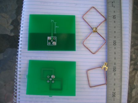
Jeff and I have just had an enjoyable day outside testing candidate antennas for the Mesh Potato. Our goal was to evaluate candidates for the internal antenna of the production Mesh Potato.
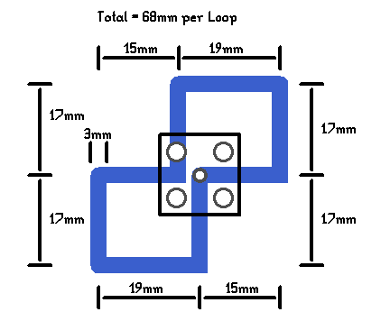
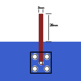
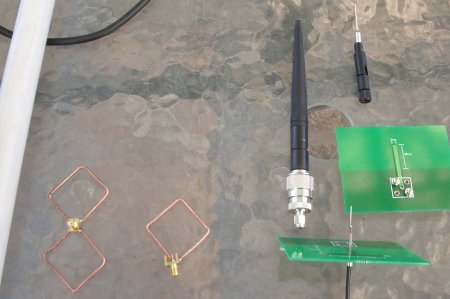
Jeff designed three types of antennas which I laid out on PCB and had fabricated locally. The three designs were a dipole, a monopole, and a biquad (single loop). We made three versions of each PCB antenna with slightly different dimensions.
I also made a some wire antennas, a monopole, a biquad (dual loop), and a quad (single loop).
Checking the Antenna Impedance
When the PCBs came back the first step was to check the impedance of each antenna. We want roughly 50 ohms impedance to ensure the maximum amount of power is transferred from the Mesh Potato transmitter to the antenna.
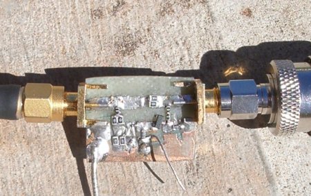
A Standing Wave Ratio (SWR) bridge can be used to measure the SWR. I used a version of the design by Erwin Gijzen, a radio Ham and Wifi experimenter. I constructed the SWR head, and measured the DC voltage from the bridge using a multimeter. The bridge compares the impedance of the antennas to a known 50 ohms impedance. If they are equal then the DC output from the bridge should be 0V. Various degrees of mis-match give different output voltages.
I constructed the bridge from double sided PCB and cut the microstrip (3mm wide on 1.6mm thick FR4) with a Dremel tool to save time. When tested it gave sensible results once I fitted a decent microwave detector diode. Unlike Erwin I couldn’t null it down to 0V with a reference 50 ohm load but it did give indicative readings that enabled me to compare our antennas to reference antennas and determine if they had a reasonable match to 50 ohms.
Here are some results:
| Load | SWR bridge output (VDC) |
|---|---|
| 50 ohm dummy | 0.5 |
| short circuit | 1.3 |
| off the shelf router antenna | 0.5 |
| 17mm PCB monopole | 0.5 |
| 20mm PCB monopole | 0.7 |
| 34mm PCB dipole | 1.3 |
| 64mm PCB biquad dual loop | 1.3 |
| 68mm PCB biquad dual loop | 1.4 |
| 72mm PCB biquad dual loop | 1.5 |
| wire biquad dual loop | 0.8 |
| wire monopole | 0.6 |
The 17mm and 20mm monopoles look good, close to the reference 50 ohm load and commercial off the shelf router antennas (which have sleeve dipole construction internally). The wire antennas also look good. The PCB dipole and PCB biquads don’t look so great.
I tuned the wire monopole to a low SWR by snipping off bits of wire, 0.5mm at a time. I started with a length of 31mm (free space quarter wavelength at 2.4 GHz) but found a good SWR at 26mm. This is probably due to the dielectric constant of the insulation on the wire affecting the wavelength.
Antenna Test Range
I constructed a test range in my back yard, along the lines discussed by Erwin. I used a Nanostation 2 at the transmitter, sending continuous 802.11b broadcast pings as described here. The antenna under test was placed about 6m away and a spectrum analyser used as the receiver. It wasn’t a very good antenna range but after some experimentation we did get surprisingly repeatable results when we compared our antennas to several control antennas.
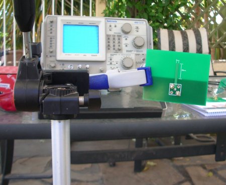
I fashioned a clamp on a tripod to hold the antennas:
However the tripod and clamp didn’t work very well. When I swapped antennas the results differed wildly in exactly the same position. It’s hard to place a 17mm printed monopole in the same position as a 80cm colinear antenna as their sizes are so different.
So instead I moved each antenna around by hand until I found the peak amplitude, which was captured by the “max hold” function of the spectrum analyser. Sounds a bit rough but gave good repeatable results, and Jeff and I achieved similar results when testing.
Path Loss
The 802.11b signal peaked at about -30dBm on the spec an. Using the Wifi power measurement method described here this means a total received power of -20dBm.
The expected received signal is:
Pr = Tx power + Tx antenna gain – path loss + Rx antenna gain – coax loss
So we plug in the numbers from the Nanostation 2, a 6m path loss and the 8dBi gain Superpass omni reference antenna we get:
Pr = 16 + 12 – 56 + 8 -1 = -19dBm
which is pretty close to what we are measuring using the spectrum analyser. If only all my calculations came out this close!
Antenna Gain Results
We used the 8dBi Superpass as a reference. We would first measure the signals from the Superpass, then save that on the screen as signal A. We would then measure the test antennas and calculate the antenna gain based on the known Superpass gain. We moved each antenna around by hand until a peak was found (the max hold function made this straight forward).
We repeated these tests several times over the day, and while the absolute levels would change 1-2dB the relative levels were always similar.
The antennas are listed in order of gain, and I would estimate the measurements have a tolerance of +/- 1dB. The RF level is the peak of the 802.11b signal on the spectrum analyser.
| Antenna | Rx Level (dBm) | Gain (dBi) |
|---|---|---|
| 15dB grid antenna | -24 | 14 |
| wire (two loop) biquad with reflector | -26 | 12 |
| 8dB Superpass | -30 | 8 |
| wire (two loop) biquad | -34 | 4 |
| wire (one loop) quad | -35 | 3 |
| wire monopole | -36 | 2 |
| 17mm PCB monopole | -36 | 2 |
| 20mm PCB monopole | -36 | 2 |
| commercial router antennas | -36 | 2 |
| 72mm PCB biquad dual loop | -40 | -2 |
Discussion
The location of the physical position where peak received signal was found was quite “sharp”. This may have been due to lobes in the signal from the Nanostation 2 or multipath.
Several commercial router antennas were tested (sleeve dipole construction), they all measured about the same. The internal design of these antennas is discussed here.
The results from the control antennas (15dB grid, 8dB Superpass, and nominal 2dB sleeve dipole commercial router antennas) are consistent with what we would expect, which gives us some confidence in the other test results.
The impedance match and gain results from the PCB biquad are poor, which suggests the antenna is not resonant at 2.4GHz. It would be nice to test this antenna on a network analyser to find out where they are resonant (please contact me if you have one – I will ship an antenna to you!) Jeff is working up a simulation of the PCB biquad to test the design. We aren’t pursuing the PCB dipole as we have a bunch of antenna candidates that perform just as well (2dBi).
The wire biquad performance with a reflector was remarkable, nearly as good as the grid antenna which is a much larger antenna. The measured gain (12dBi) is consistent with other peoples results for this antenna.
Jeff and I really liked the wire antennas due to their performance and simplicity. They are easy to make: in production they could be bent up on a jig on 10 seconds from stiff copper wire then soldered to the Mesh Potato motherboard. One small problem with the dual loop biquad wire antennas is a feed arrangement – a small piece of coax would be needed to reach the central feed point. We don’t want the antenna wire directly over the PCB, as this would affect performance. The single loop wire quad is simpler in this regard, as it could be attached at one corner to the PCB.
The PCB monopoles perform well and are very simple, just a 17mm x 3mm track on the PCB next to a good chunk of ground plane. Virtually zero cost to add to the Mesh Potato motherboard. Both the 17mm and 20mm versions worked well, which suggests a relatively wide bandwidth and a high tolerance to small variations in manufacture like dieletric constant of the PCB substrate. Antennas fabricated on PCB are physically smaller than their wire cousins as the signals travel slower which means a smaller wavelength for a given frequency.
Wire single and dual loop biquad/quad antennas had above average gain and some directivity, with both peaks and nulls evident as they were rotated. Is directivity a good thing for a mesh router? You might enhance the signal of one node but null out the signal from another. I am not sure.
The higher gains of some antennas look attractive but may not be useful in practical mesh networks. To achieve the highest gain required careful adjustment of the antenna position. This is fine in a traditional point-point Wifi link, but in a mesh network their are multiple nodes we want to talk to. So if you peak the response to one node, you may dip the response to another. I guess it depends on how many nodes you want to talk to.
The reflector was a piece of blank PCB about 20cm x 20cm. It was moved back and forth behind the antenna until a peak was found (usually at around 15-20mm). All antennas improved by at least 4dB with the reflector, the wire biquad improved by 6-8dB. David C has suggested a slide-in reflector arrangement to give a choice between omni and directional antennas. These tests confirm David’s suggestion is a good one, if a precise way to mounting the reflector can be found.
Here are some of the antennas tested grouped by gain.
